
Measuring distortion with software

The case with the “Chinese” Quad 909 was the first occasion we worked with a software based distortion analyzer.
I used to work with a Sound Technology 1710A. The unit needs calibration and some repair; I have sent mails to ST, but no response until now. Just a calibration is a staggering 995 dollar or so, ex P&P, if they accept the work. Then I realized that even if they were willing to repair the unit, the performance will not be good enough to measure modern or modified vintage equipment. So we moved on.
Distortion analyzers like the ST are based on wideband AC RMS meters. First you measure the output signal of the amplifier under test, then you remove the test tone and measure the residue. Eventually you can calculate the distortion. This is off course distortion including noise.
The software distortion analyzers are based on a spectrum analyzer program and analog-to-digital and digital-to-analog converters. This type of analyzers measures the individual frequency components, the rest is “only” calculation!
Spectrum analyzers existed in the pre digital days, but they where very expensive.
The theory behind this is the fact that every repeating signal can be decomposed in so called harmonics and the basic frequency component. To measure amplifiers you also need a signal gen
 erator and an oscilloscope in (preferable) one software package. I started with a freeware solution from Sillanum Soft and the standard sound card in my PC. The results were very promising. The next phase was a high quality, 24 bit, 192 KHz sampling rate, low distortion, soundcard with balanced outputs (ESI Juli@). The results were more than ok. Because the Sillanum Soft package only has the basic functionality, I bought a package from Virtins Technology and built a proper brake out box with volume controls, a variety of connections and a possibility to connect load resistors and other lab equipment. To get more speed (calculation power) from the PC, I also installed a 64 bit operating system (dual boot option).
From the website of Audio Precision, a high end distortion analyzer manufacturer, I downloaded two very useful documents. The Audio Measurement Handbook and a large document titled "How to write and read audio specifications". By reading and digesting the last document you will find that most specifications of commercial audio equipment are not complete and meaningless in most cases! Even our Quad heroes wrote those kind of specs!

A practical case: measuring a Dada Electronics revised Quad 303
See the specifications in the picture. First I checked the distortion. Quad measured at a strange frequency of 700Hz. Also the term “unrestricted bandwidth” is undefined. What does ”up to 45 watt” mean in real terms of voltage and watts? My own settings: 1 KHz test signal, bandwidth: 20Hz to 20 KHz and 45 watt in 8 ohm loads, both channels driven and loaded. As you can see the specification of 0.0
 3% is easily met. If you remove or lower the load the result is spectacular. Very low distortion indeed.
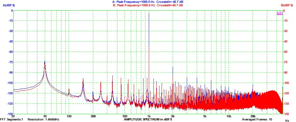
The next measurement was the crosstalk. Quad did not specify the output parameters. As you can see, with the channels loaded with 8 ohm and the power at 45 watts, the channel separation is below modern standards. Only good enough for vinyl replay or FM broadcasts. If you remove or decrease the load, it is ok.
So there are people who say the 303 is the best Quad amplifier ever made. We don’t agree if you use the 303 with modern digital source material combined with high volume settings. This is one of the reasons we advise to monoblock a 303 or use it in a bi-amp application per channel. The load dependent cross talk can influence the stereo soundstage.
The next myth: high bias current
In the Quad service manual it is stated that the DC bias current of the power transistors must be between 10mA and 5mA. A popular “mod” is increasing the current to 35mA and in some cases even higher. Well, in real life the distortion is only 0.05% at a bias current of 0.5mA. At 5mA it is 0.01% and will not get lower at higher bias currents. Also the spectrum analyzer will not give a better (cleaner) picture at high levels of bias current. So Quad was (is) right! For practical reasons, stability of the circuit, 10mA is a good value for the bias current.
Joost Plugge
Virtins Technology
Sillanumsoft
ESI
Audio Precision
Labels: amplifiers, audio, Quad, Quad 306 Vintage Amplifier, vintage
posted by Stefaan @ 11:49 AM
0 comments
![]()
![]()


