Dada is now reseller for DACT & Flashbacksales


only wants the best suppliers.
posted by Stefaan @ 12:58 AM
0 comments
![]()
![]()
This Blog is about revising/upgrading the vintage Quad 33 to 909 amplifiers and the Revox taperecorders. Audio electronics and High End Hifi are also absolutely "on-topic" here. All pictures on this site (except the schematics) are Copyright Dada Electronics. You can use them after a written agreement (via e-mail) with the author. For Contact-information see www.dadaelectronics.eu

posted by Stefaan @ 12:58 AM
0 comments
![]()
![]()
Joost, who is the development-engineer (and CTO) of Dada/JP Engineering, wanted to give you a first impression of the starting-points why we are developing the new 405 High-end boards.
There are five sources for serious 405 modifications:
The Quad 405 service manual.
In this manual the history of the 405 in terms of official factory modifications is fully documented. Also are most of the diagrams, part lists and printed circuit board layouts present.
It can give you ideas for retrofitting modifications to the 405-1 and early 405-2 models.
(the 405 service manual is available for free on simple e-mail demand from info@dadaelectronics.eu)
The Bernd Ludwig paper.
Bernd Ludwig was (as far as I know) the first one who described the 405 circuit in full detail, suggested three upgrades and shared a lot of (his) general knowledge about the 405 circuit. The paper covers the following subjects.
DC- Daylight Web pages.
Using the work of Bernd Ludwig as a basis, Keith Snook suggested two important modifications:
Also Keith suggested more practical ways to implement Bernd Ludwig's modifications, completed the set of diagrams of the 405, introduced his own fully modified 405-3, ( my number) and discovered a fault in the Service Documentation concerning the diagram of the 405-2 current limiter.
The designs of the Quad 240/306/510/520 and 606.
This give you some ideas how a fully developed 405 could look. Quad themselves did only one substantial upgrade, the 405-2 modification.
The designs of Tiberiu Vicol.
Although he made very extensive redesigns, some parts will fit as an upgrade to a more or less normal 405. The quality of his work is very good, so keep track!
The JPE / Dada design.
Instead of producing an endless number of prototypes, during the design stage I decided to built the two circuits, the Non and Inverted input circuit, in a computer simulation tool. I modelled the full input circuit including the mid section filter stage. The rest of the circuit is simulated by a non inverting Opamp. The latter one providing the necessary gain and the DC feedback circuit. See the diagram for details. Both circuits emulate the standard 405 with an input sensitivity of 500mV, and a overall gain of 56.
Some observations:
The gain of the input Opamp circuit is 15, the input impedance is 20K at 1kHz. When changing the gain, you also have to change the time constants of the local and overall feedback loops. When using the model you can play with the values of the components and see the results on the spot. To preserve the overall frequency behaviour, follow the recipe of Bernd Ludwig. If you change some values, i.e. to increase the DC suppression, it also has effects on the LF response. The behaviour of the circuit is plain Opamp technique, no magic or surprises.
With the non inverted input circuit, which is a far better idea as a first stage than a inverted one, you only have to replace two components, to change the gain and the time constant of the overall feedback circuit. In a inverting circuit the noise is higher and in general the input impedance is low. By changing the power supply voltage (asymmetric), testing of the DC feedback circuit can be done. The non inverted model performs ok in this respect. I did not build a complete 405 circuit, I believe the current dumping principle works fine!
The model and our own input gave the following functional/technical demand for the prototype
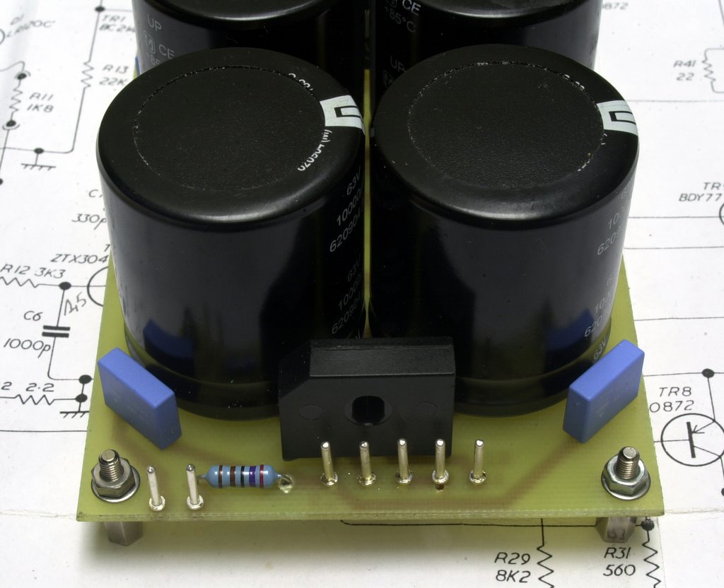
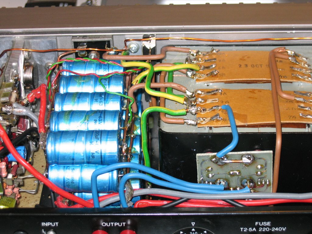
The power supply
The upgrade that Bernd and Keith suggest is replacing the PSU capacitors with fresh bigger ones and bypassing the capacitors with small caps to reduce the HF impedance. Although this is good advise in itself, we have to take the development of the PSU a step further.
The active ground DC protection will only work with a fully separated double power supply. But the big sonic reason for building a double supply is the following: Crosstalk! A standard 405 have a channel separation of only -60dB at 10KHz. So the crosstalk signal is 20dB higher than the distortion. The double supply in combination with a careful internal cable layout and building the amplifier as a four-pole device, so no ground connections, can reduce the crosstalk level to at least -90dB across the audio spectrum. The four pole approach also reduces ground loops, with a standard 405 there is always a ground loop, formed by the Cinch or Din input cables. For safety reasons the power supply cord must be connected to a wall socket with a proper earth connection, so touching the case is not a hazardous job.
Joost
posted by Stefaan @ 11:46 PM
4 comments
![]()
![]()

posted by Stefaan @ 6:07 PM
0 comments
![]()
![]()
posted by Stefaan @ 8:57 PM
0 comments
![]()
![]()